← Engineering
Independent extension of a guided project
Airflow Around a Spoiler: CAD + CFD
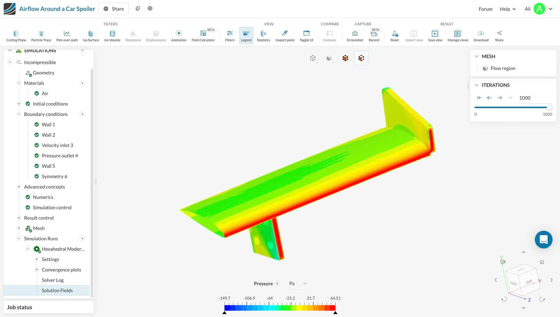
I designed an automotive spoiler in SolidWorks and ran the full CFD pipeline on it in SimScale, including a moving-floor boundary condition to represent the road.
- Project
- Airflow Around a Spoiler: CAD + CFD
- Sheet
- 02 / 04
- Date
- Jan 2026
- Type
- Engineering
Inlet velocity
10 m/s
Turbulence model
k-ω SST
01
Setup
I modelled the spoiler myself in SolidWorks, then built and labelled the surrounding flow region in SimScale. The case was steady, incompressible air with k-ω SST turbulence.
- Boundary conditions: no-slip on the spoiler, slip walls on the outer boundaries, velocity inlet and pressure outlet, a moving floor at free-stream speed, and a symmetry plane to halve the computation.
- Hex-dominant mesh with a refinement box around the spoiler.
02
Results
Pressure peaked and velocity dropped at the leading edges, velocity was highest over the surface, and turbulent kinetic energy rose in the wake behind the trailing edge. That matches expected aerodynamic behaviour and confirms a physically consistent setup.